Plc program for automatic mixing control in a tank Tank mixing plc control program diagram The diagram shown below illustrates a mixing tank
Mixing Tank - JXSC
Mixing tank / storage tank Flocculation treatment process water basin wastewater mixing plant Mixing: unit operation
Schematic constraints mpc input scheme
China heating mixing tank photos & picturesPlc program for mixing tank Mixing plc tiliScheme of the mixing tank.
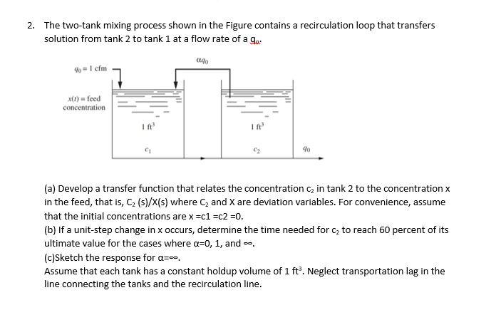
Schematic diagram of the two tank mixing process.Flocculation basin Flocculation mixerSolved 2. the two-tank mixing process shown in the figure.

Automatic batch mixing tank with plc ladder logic programming
Stainless steel mixing tank with agitator emulsifying mixing blendingThe diagram shown below illustrates a mixing tank Mixers for dissolved air flotation (daf) systemsSchematic diagram of the two tank mixing process..
Geometry of the mixing tank the above schematic diagram figure21. in an automatic mixing operation the sequence of Solved 3. your supervisor asked you to design 1. a rapid-mixSolved 3. calculate "size of rapid mixing tank" and hp of.

Solved consider the two-tank mixing process shown in the
Solved consider the two-tank mixing process shown in theFt3 recirculation solution transfers Mixing tankMixing daf air flotation dissolved coagulation flash rapid wastewater coagulant chemical mixers systems system industrial chemicals particle promotes reactions dosages.
Solved tutorial: chemical mixing tank process description:Plc program for mixing tank Solved the schematic of a mixing tank is shown below. it hasSolved tutorial chapter 5 and 6construct a typical mixing.

Tank plc mixing automatic program controlling diagram ladder logic programming control level process system sensor instrumentation circuit problem
Mixing tankMixing tank diagram Process tank / mixingMixing tanks designed for process results.
5 . schematic of mixing tank internal components1. design a rapid mixing tank by using the following Rapid mixing in water treatmentTank mixing storage inora flow chart.

Tank mixing sequence
.
.

Solved Tutorial Chapter 5 and 6Construct a typical mixing | Chegg.com

PLC Program for Mixing Tank - Sanfoundry

1. In an automatic mixing operation the sequence of | Chegg.com

flocculation-tanks - Dynamix Agitators Inc.

Mixing Tank - 陕西宏达实业有限公司

Mixing tank Diagram | Quizlet
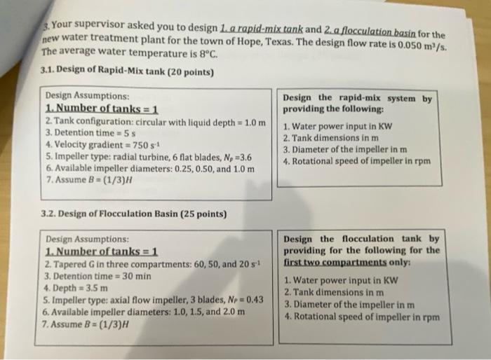
Solved 3. Your supervisor asked you to design 1. a rapid-mix | Chegg.com