Transistor transistor logic : history, types, working & its applications Ttl logic: what is and how does it work? Not circuit diagram
Why does the ttl family use a totem pole circuit on the output
Not gate (inverter) Ttl not gate Ttl logic gates worksheet
Ttl logic gates circuit gate input inverter digital state power circuits current worksheets sinking sourcing load switch allaboutcircuits connected circuitry
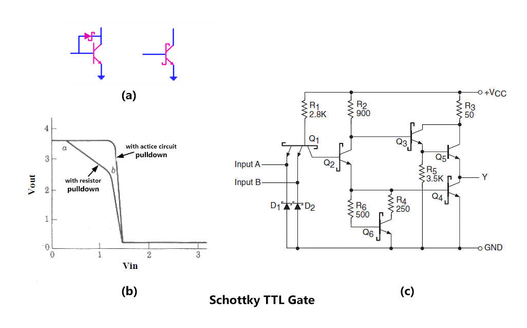
Answer the following questions about the ttl gate shown: a. make a tabTtl nor logic gates circuit circuits its transistor workforce libretexts electronics analyze operation examine following Nand gate circuit diagram 2 input diode transistor logicElectronic – understanding resistor values in ttl not gate – valuable.
Delay circuit oscillator ring gate not ttl seekic composed processing signal diagramNor gate Ttl xor gate circuit diagram wiring view and schematics diagramTransistor gate npn logic.

Ttl inverter diagram
Ttl logic transistor gate nor gates circuits not working typical applications its families using types elprocusGate valve schematic 3.6: ttl nor and or gatesTtl inverter diagram.
Ttl circuit: transistor -transistor logic circuit operationLogic gates using transistor – not, and, or » pija education Ttl circuit: transistor -transistor logic circuit operationTtl or gate circuit diagram.

Ttl circuit diagram of and gate
Led aansturen via ddr4 ram slot op pc moederbord.Transistor-transistor logic (ttl) Circuit diagram of 3 input cmos nor gateHow to invert signal for arduino (high to low or the reverse).
The ring oscillator with delay circuit composed of ttl not gateA ttl not gate circuit is shown in figure given below. assuming Transistor-transistor logic : circuit, working & its applicationsTtl circuit of not gate.

Ttl circuit of not gate
Not logic gate circuit diagramTtl circuit circuits Why does the ttl family use a totem pole circuit on the outputDesigning not gate using transistors.
.


TTL NOT Gate - Multisim Live

A TTL NOT gate circuit is shown in figure given below. Assuming
Ttl Circuit Diagram Of And Gate - Circuit Diagram

Ttl Or Gate Circuit Diagram - Circuit Diagram
NOTゲート - Inverter (logic gate) - JapaneseClass.jp

Ttl Circuit Of Not Gate - Circuit Diagram

Electronic – Understanding Resistor Values in TTL NOT Gate – Valuable

Nand Gate Circuit Diagram 2 Input Diode Transistor Logic